In this part we’ll define Power for AC circuits, we’ve had all the tools now for a while, but just never applied them.
Power in AC circuits and be divided into three categories:
- Resistive load $(\theta = 0)$.
- Inductive load $(Z = \omega L \angle 90^{\circ})$.
- Capacitive load* $(Z = \dfrac{1}{\omega C} \angle -90^{\circ})$.
Resistive Load
When we have a resistive load, meaning no phase shift. Then our Voltage and Current are: $$ V(t) = V_m cos(\omega t) \newline I(t) = I_m cos(\omega t) $$
Which, naturally means our power is: $$ P(t) = V_m I_m cos^2(\omega t) $$
This is the so-called, instantaneous power.
Our average power is: $$ P_{avg} = \dfrac{V_m I_m}{2} $$
Recall that the Root-mean-square is: $$ V_{rms} = \dfrac{V_m}{\sqrt{2}} $$
$$ I_{rms} = \dfrac{I_m}{\sqrt{2}} $$
This also means: $$ P_{avg} = V_{rms} I_{rms} $$
Inductive Load
In an inductive load, the voltage leads the current by $90^\circ$. $$ V(t) = V_m cos(\omega t) \newline I(t) = I_m cos(\omega t - 90^\circ) $$
Or, we can write $I(t)$ as: $$ I(t) = I_m sin(\omega t) $$
Which means, our instantaneous power is: $$ P(t) = V_m I_m cos(\omega t) sin(\omega t) $$
Using one of the trigonometry identities: $$ P(t) = \dfrac{V_m I_m}{2} sin(2\omega t) $$
Our average power then? Well, the period of our power, $P$, is half the period of $V$ or $I$.
This means that when either $V(t)$, or $I(t)$ are equal to 0, so is $P$.
Therefore, the average power will also be zero! $$ P_{avg} = 0 $$
Capacitive Load
In a capacitive load, the current now leads by $90^\circ$. $$ V(t) = V_m cos(\omega t) \newline I(t) = I_m cos(\omega t + 90^\circ) $$
We can again rewrite $I(t)$ as: $$ I(t) = I_m -sin(\omega t) $$
Which means our instantaneous power is: $$ P(t) = -V_m I_m cos(\omega t) sin(\omega t) $$
Or using the same trigonometry identity: $$ P(t) = -\dfrac{V_m I_m}{2} sin(2\omega t) $$
Since we’ve only flipped our signed, the average power behaves the same $$ P_{avg} = 0 $$
Average Power Example
Let’s try to understand the average power with an example:
If we have: $$ Z_{L} = 8 - j11 \newline I = 5 \angle 20^\circ $$
What’s average power in $Z_{L}$?
We know that the reactive part is going to be zero: $$ P_{avg:\ Z_{reactive}} = 0 $$
The resistive part: $$ P_{avg:\ Z_{resistive}} = \dfrac{V_m I_m}{2} $$
Which we can rewrite with Ohm’s law: $$ P_{avg:\ Z_{resistive}} = \dfrac{I_m^2 R}{2} $$
$$ P_{avg:\ Z_{resistive}} = \dfrac{(5^2) \cdot\ 8}{2} = \boxed{100 W} $$
Power in AC circuits - general
Let’s now write this as general we can: $$ V(t) = V_m cos(\omega t + \theta_V) \newline I(t) = I_m cos(\omega t + \phi_I) $$
Which means our instantaneous power: $$ P(t) = V_m I_m cos(\omega t + \theta_V) cos(\omega t + \phi_I) $$
We can rewrite this as: $$ P(t) = \dfrac{1}{2} V_m I_m cos(\theta_V - \phi_I) + \dfrac{1}{2} V_m I_m cos(2 \omega t + \theta_V + \phi_I) $$
As we can see, this has one constant part and one periodic part.
This means our average power is: $$ P_{avg} = \dfrac{V_m I_m}{2} cos(\theta_V - \phi_I) $$
Or using RMS: $$ P_{avg} = V_{rms} I_{rms} cos(\theta_V - \phi_I) $$
Different types of power in AC
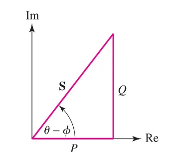
Since we always deal with a complex part and a real part in AC, we can also define different types of power:
- Real Power: $P = V_{rms} I_{rms}\ cos(\theta_V - \phi_I)\ [W]$
- Unit is in Watts, if this is purely resistive, meaning no phase shift, $P = V_{rms} I_{rms}$.
- Reactive Power: $Q = V_{rms} I_{rms} sin(\theta_V - \phi_I) [VAR]$
- Unit is in Volts Amperes Reactive, if purely resistive, $Q = 0$.
- Complex Power: $S = P + jQ$ or in polar form, $S = V_{rms} I_{rms} \angle \theta_V - \phi_I [VA]$
- Unit is in Volt Ampere.
- Apparent Power: $|S| = V_{rms} I_{rms} [VA]$.
- Unit is in Volt Ampere.
This also means that: $$ P^2 + Q^2 = (V_{rms} I_{rms})^2 $$
Power Factor
The last thing we’ll talk about is the so-called power factor.
We define the power factor as: $$ PF = cos(\theta_V - \phi_I) \leq 1 $$
We call the angle, for the power angle: $$ \text{Power Angle} = \theta_V - \phi_I $$
Which means we can define the power factor as: $$ PF = \dfrac{P}{|S|} $$

The power factor and the power angle say a lot about the type of circuit we have.
An inductive load will always have a positive power angle, on the other hand, a capacitive load will have a negative power angle!
Power Relationships
Now, with all these tools, let’s write down some relationships. There’s a lot.
$$ P = V_{rms} I_{rms} = I_{rms}^2 R = \dfrac{V_{rms}^2}{R} $$
Note, here $X$ is equal to the reactance $$ Q = I_{rms}^2 X = \dfrac{V_{rms}^2}{X} $$
$$ S = P + j Q $$
$$ S = V_{rms} I_{rms} \angle \theta_V - \phi_I $$
$$ S = \dfrac{V_m I_m}{2} \angle \theta_V - \phi_I $$