In this part we’ll cover circuit response, filter and amplifiers.
Transfer Function
Recall from the last part that, the transfer function is defined as: $$ H(f) = \dfrac{V_{out}}{V_{in}} $$
Let’s find the transfer function of this circuit:
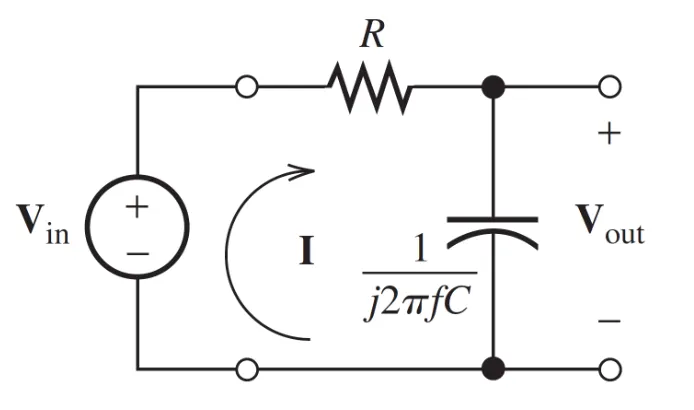
Let’s find $V_{out}$ $$ \begin{align*} V_{out} & = I \cdot\ Z_C \newline & = \left(\dfrac{V_{in}}{Z_R + Z_C}\right) Z_C \newline & = \left(\dfrac{V_{in}}{R + \dfrac{1}{j2\pi fC}}\right) \left(\dfrac{1}{j2\pi fC}\right) \end{align*} $$
Which means that $H(f)$: $$ \begin{align*} H(f) & = \dfrac{V_{out}}{V_{in}} & = \dfrac{\left(\dfrac{V_{in}}{R + \dfrac{1}{j2\pi fC}}\right) \left(\dfrac{1}{j2\pi fC}\right)}{V_{in}} \newline & = \cdots & = \dfrac{1}{1 + j2\pi fRC} \end{align*} $$
We can define $f_B$ as: $$ \begin{align*} f_B & = \dfrac{1}{2\pi RC} \end{align*} $$
Which means: $$ \begin{align*} H(f) & = \dfrac{1}{1 + j \left( \dfrac{f}{f_B} \right)} \end{align*} $$
Therefore, the magnitude of $H(f)$ is: $$ \begin{align*} |H(f)| & = \dfrac{1}{\sqrt{1 + \left( \dfrac{f}{f_B} \right)^2}} \end{align*} $$
The angle: $$ \begin{align*} \angle{H(f)} & = - \arctan \left(\dfrac{f}{f_B} \right) \end{align*} $$
Decibels
We all have heard (yes, pun intended) of decibels. Let’s properly define what decibels are: $$ |H(f)|_{dB} = 20 log(|H(f)|) $$
Amplifier
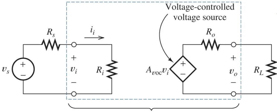
Is just as the name suggests: $$ V_{0}(t) = A_{v}V_{i}(t) $$
Note that, $A_{v}$, can be of any sign, which means we also have inverting amplifiers!
A typical model would look something like:
Operational Amplifier (Op-Amp)
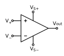
An Op-Amp looks like:
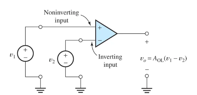
We use the Op-Amp like:
An Ideal Op-Amp has:
- Infinite input impedance
- Infinite gain for differential signal
- Zero gain for the common-mode signal
- Zero output impedance
- Infinite bandwidth
Differential signal: $$ V_d = V_1 - V_2 $$
Common-mode signal: $$ V_cm = \dfrac{1}{2} \left(V_1 + V_2 \right) $$
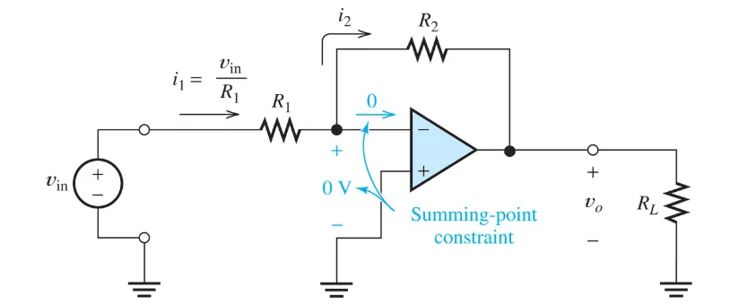
Let’s take a look at this Op-Amp circuit: $$ I_1 = I_2 = \dfrac{V_{in}}{R_1} $$
KVL: $$ 0 + I_2 R_2 + V_{o} = 0 \newline I_2 = - \dfrac{V_{o}}{R_2} = \dfrac{V_{in}}{R_1} $$
Which means: $$ A_{v} = \dfrac{V_{o}}{V_{in}} = \boxed{- \dfrac{R_2}{R_1}} $$
Let’s take a look at this Op-Amp:
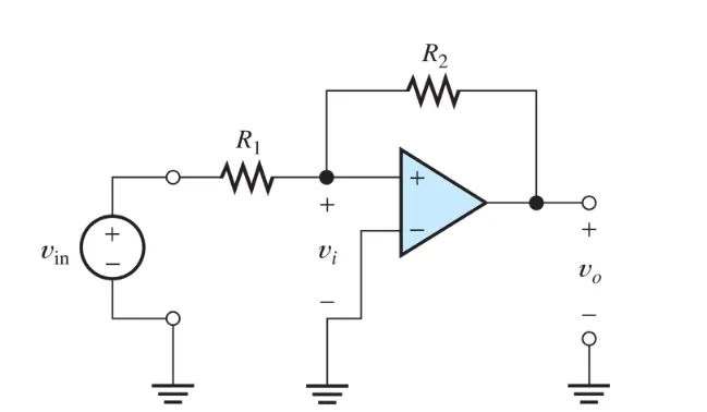
Here we’ll quickly discover that we have positive feedback. Positive feedback saturates the output - which means we can not use the derived formulas from above!
Always check if there is positive or negative feedback.
For non-inverting amplifiers, we get: $$ A_{v} = \dfrac{V_{o}}{V_{in}} = \boxed{1 + \dfrac{R_2}{R_1}} $$
So, steps to analyze an ideal Op-Amp circuit:
- Verify that negative feedback is present
- Assume that the voltage between the terminals and input current are forced to 0.
- Apply standard circuit analysis principles (KCL, KVL, and Ohm’s Law).