Sequential Circuits
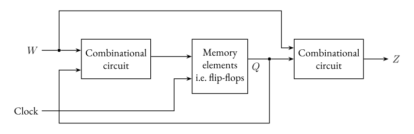
When we usually look at circuits we have an input and output that are independent of each other. In a sequential circuit, as the name suggests, we have a sequence. Meaning we feed back our output as input.
We can easily define this as: Our output no longer depends on the present input - but on the past behavior of the circuit.
State-Holding Memory Elements
We’ve encountered latches and flip-flops before, they have a so-called memory element to them.
Let’s quickly go over the difference between a latch and a flip-flop.
- Latch
- Latches are level-sensitive
- When the clock is high, the latch is transparent (
output <= input) - When the clock is low, the latch keeps its previous state.
- When the clock is high, the latch is transparent (
- Latches are level-sensitive
- Flip-flop
- Flip-flops are edge-sensitive
- Data passes through only on a rising/falling edge of the clock.
- Flip-flops are edge-sensitive
Latches are also cheaper to implement than flip-flops, but flip-flops are easier to use in designs than latches.
We’ll primarily look over the so-called D flip-flop.
D Latch
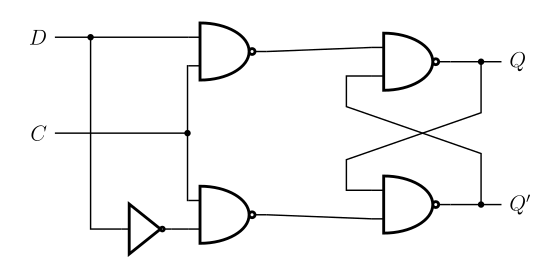
| C | D |
|---|---|
| 0 | X |
| 1 | 0 |
| 1 | 1 |
As we can see, we just “store” the value we have set. To build a D flip-flop, we can use a master-slave architecture. We could also use a positive edge triggered architecture.
Setup and hold time
The D input signal must be stable when clock is changing from (setup). The same D signal must remain stable for a while after the clock change (hold).
Good to note is that the reset of a D flip-flop can be asynchronous or synchronous.
Registers, Shift Registers and Counters
A register is just a circuit which contains N flip-flops. Whilst a flip-flop stores 1-bit information.
A register will contain N-bit information. Usually a common clock is used for each flip-flop in the register.
Shift registers are just as the name implies, you shift around the given input into each flip-flop.
Example 1 (Sequence detector)
We can use what we’ve learned to build a sequential circuit which detects two 1’s in a row in a sequence.
If we go back to our general picture of a sequential circuit, and list our specifications:
- The circuit should have one input, , and one output, .
- All changes occur on positive edge of the clock.
- The output, , should be equal to 1 if in two immediately preceding clock cycles the input was 1. Otherwise, should be 0.
If we plan our state diagram we can say that:
We begin in state A when the power is on or during a reset signal. We keep being in state A as long as .
When , we move to state B.
If , then we move back to state A. If , then we move to state C and set .
In state C, if , then move back to state A, if , remain in state C.
After this we draw our state table, followed by the Karnaugh maps that follow from the state tables.
Then we can at last implement this circuit.
- Specifications
- Derive the states, and create a state diagram
- Create a state table
- (State minimization)
- State assignment
- Choose flip-flops
- Derive logic expressions for state and outputs
- Implementation