In this part we’ll define Power for AC circuits, we’ve had all the tools now for a while, but just never applied them.
Power in AC circuits can be divided into three categories:
- Resistive load (θ=0).
- Inductive load (Z=ωL∠90∘).
- Capacitive load (Z=ωC1∠−90∘).
Resistive Load
When we have a resistive load, meaning no phase shift. Then our Voltage and Current are,
V(t)I(t)=Vmcos(ωt),=Imcos(ωt).
Which, naturally means our power is,
P(t)=VmImcos2(ωt).
This is the so-called, instantaneous power.
Our average power is,
Pavg=2VmIm.
Recall that the Root-mean-square is,
VrmsIrms=2Vm,=2Im.
This also means,
Pavg=VrmsIrms.
Inductive Load
In an inductive load, the voltage leads the current by 90∘,
V(t)I(t)=Vmcos(ωt),=Imcos(ωt−90∘).
Or, we can write I(t) as,
I(t)=Imsin(ωt).
Which means, our instantaneous power is,
P(t)=VmImcos(ωt)sin(ωt).
Using one of the trigonometry identities,
P(t)=2VmImsin(2ωt).
Our average power then? Well, the period of our power, P, is half the period of V or I.
This means that when either V(t), or I(t) are equal to 0, so is P.
Therefore, the average power will also be zero!
Pavg=0
Capacitive Load
In a capacitive load, the current now leads by 90∘,
V(t)I(t)=Vmcos(ωt),=Imcos(ωt+90∘).
We can again rewrite I(t) as,
I(t)=−Imsin(ωt).
Which means our instantaneous power is,
P(t)=−VmImcos(ωt)sin(ωt).
Or using the same trigonometry identity,
P(t)=−2VmImsin(2ωt).
Since we’ve only flipped our sign, the average power behaves the same,
Pavg=0.
Example 1 (Average power)
Let’s try to understand the average power with an example:
If we have,
ZLI=8−j11,=5∠20∘.What’s the average power in ZL?
We know that the reactive part is going to be zero,
Pavg,Zreactive=0.The resistive part,
Pavg,Zresistive=2VmIm.Which we can rewrite with Ohm’s law,
Pavg,Zresistive=2Im2R=252⋅8=100 W.Power in AC circuits - general
Let’s now write this as generally as we can,
V(t)I(t)=Vmcos(ωt+θV),=Imcos(ωt+ϕI).
Which means our instantaneous power,
P(t)=VmImcos(ωt+θV)cos(ωt+ϕI).
We can rewrite this as,
P(t)=21VmImcos(θV−ϕI)+21VmImcos(2ωt+θV+ϕI).
As we can see, this has one constant part and one periodic part.
This means our average power is,
Pavg=2VmImcos(θV−ϕI).
Or using RMS,
Pavg=VrmsIrmscos(θV−ϕI).
Different types of power in AC
Since we always deal with a complex part and a real part in AC, we can also define different types of power:
Definition 1 (Types of power)
- Real Power: P=VrmsIrmscos(θV−ϕI) [W]
- Unit is in Watts, if this is purely resistive, meaning no phase shift, P=VrmsIrms.
- Reactive Power: Q=VrmsIrmssin(θV−ϕI) [VAR]
- Unit is in Volts Amperes Reactive, if purely resistive, Q=0.
- Complex Power: S=P+jQ or in polar form, S=VrmsIrms∠(θV−ϕI) [VA]
- Apparent Power: ∣S∣=VrmsIrms [VA].
This also means that,
P2+Q2=(VrmsIrms)2.
Power Factor
The last thing we’ll talk about is the so-called power factor.
Definition 2 (Power factor)
We define the power factor as,
PF=cos(θV−ϕI)≤1.We call the angle the power angle,
Power Angle=θV−ϕI.Which means we can define the power factor as,
PF=∣S∣P.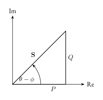 Figure 1: The power triangle.
The power factor and the power angle say a lot about the type of circuit we have.
An inductive load will always have a positive power angle, on the other hand, a capacitive load will have a negative power angle!
Power Relationships
Now, with all these tools, let’s write down some relationships. There’s a lot.
P=VrmsIrms=Irms2R=RVrms2
Note, here X is equal to the reactance,
Q=Irms2X=XVrms2
S=P+jQ=VrmsIrms∠(θV−ϕI)=2VmIm∠(θV−ϕI).